ESS (Electromechanical Systems Simulator)
Silahkan lihat video tutorialnya :disini
1. Video Review software VIDEO REVIEW
2. Video Cara menggunakan software DISINI
3. Video Project 1
4. Video Projrct 2
DOWNLOAD APLIKASI ESS :DISINI
(manual Book)
Daftar Isi:
- About
- Using Simulator
- User interface
- Working with files
- Design Command Circuit
- Motor Circuit Types
- Working with Motor Circuits
- Run Designed Circuit
- Print Circuit
- Electromechanical Systems Simulator Examples
- Info
About
Electromechanical Systems Simulator (ESS) is used to design and analyse electromechanical control Systems. These systems are highly used in industry to control processes machines. Also there is a course which studied at collages, universities and technical schools related with electromechanical control systems.
Simulator is a program that behaves like a real system giving all responses of it. This simulator is developed for designing electromechanical systems, testing them and monitoring their behaviours.
Using Simulator
User interface
Simulator have very simple interface. All buttons located at the top of the program. (Figure 1)

Figure 1: User interface
The work space is constructed in grid form so that drawing can be made more easily and smoothly. It contains of two red lines which represents electrical fuse and neutral fuse. Circuit is drawn between these lines inform of ladder diagram.
Working with files
There are simple tasks to handle with files like opening a new file, opening an existing file and saving modified file.
To open a new file simply click on  New file button located at the tool bar or from menu combination File -> New
New file button located at the tool bar or from menu combination File -> New
To open an existing file click on  Open File button or access open file dialog window from File - Open menu. On dialog window find file to open and click Open button.
Open File button or access open file dialog window from File - Open menu. On dialog window find file to open and click Open button.
Before opening any file program prompts to save changes made on an existing file if there are such.
To save file click on  Save button or click on File -> Save File menu. For saving file with different name click on File -> Save as menu. On opened dialog window write file name you wish to give to file and click Save button.
Save button or click on File -> Save File menu. For saving file with different name click on File -> Save as menu. On opened dialog window write file name you wish to give to file and click Save button.Design command circuit
Circuit components and their symbols
 Contactor
 Normally opened contact
 Normally closed contact
 Start button
 Stop button
 Jog button
 Limit switch
 Time relay (on delay)
 Time relay (off delay)
 Lamp
Lamp
To design a command circuit you need add components and connect them properly. To add component simply click on component you wish to add and drag it to its desired position and click again to release component. Once component added you can easily move it by dragging pressed on it and releasing in desired position.
To give appropriate name for component click on the label located at the top of component and type new name on it. All components must be named for running circuit. Name for open and closed contactors is selected among contactors and time relays. Therefore contactors and time relays must be named before. Time relays have their timer located at the bottom of component. To set timer, click on timer and type new value.

To change colour of lamp right click on lamp and select new colour.
To draw a connection line between two components move your mouse pointer to connection point of component. When connection point appears press left button of mouse on that point and drag your mouse to other connection point, line or node. When connection point appears release mouse button. While drawing line it will appear as blue thick line. When connection made line will be converted to black otherwise it will remain as blue. Once connection line drawn you can easily move it by dragging pressed on it and releasing in desired position.
To delete any component or line select it by pressing CTRL key. You can select many components and lines while pressing CRTL key. Selected components will appear in frame and lines will be converted to red. When you select component, lines connected to that component also will be selected. After selecting click on  Delete button at tool bar or press delete key on keyboard. To deselect components click on any component without pressing CTRL key.
Delete button at tool bar or press delete key on keyboard. To deselect components click on any component without pressing CTRL key.Motor Circuit Types
There are 9 selected motor circuit types that mostly used in laboratory.
One phase induction motor with manual switch
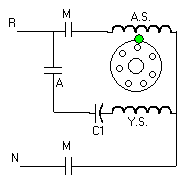
One phase induction motor with automatic switch
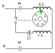
Three phase induction motor
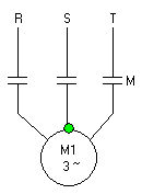
Three phase induction motor with reversing direction circuit.
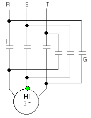
Star-delta controlled three phase induction motor
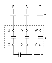
Motor circuit with single resistance starter
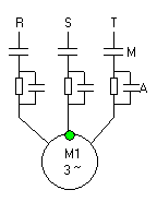
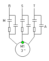
Motor circuit with double resistance starter
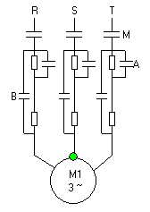
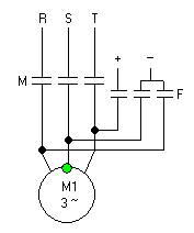
Three phase induction motor with dynamic brake circuit
Working with Motor Circuits
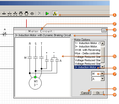
Simulator has some predefined motor circuit types. You can easily add them to your project. To add motor circuit click on  Motor Circuit button on tool bar
  . Also it is possible to access motor circuit rom View -> Motor Circuit menu. When motor circuit window opened select motor circuit which you want to add to your project from Motor Options panel
  . Selected motor circuit will appear on motor circuit window
  and its title at the top
  . Select appropriate relays for contactors from combo boxes
  on motor options panel. Click Ok button
  to save changes on motor circuit. To cancel them click Cancel button
  . If Motor Options panel is hidden, use Show/Hide button to make it visible
  . You can move Motor circuit window by pressing and drugging its outer frame
  . To hide motor circuit click on Motor Circuit button located on tool bar .
Motor Circuit button on tool bar . Also it is possible to access motor circuit rom View -> Motor Circuit menu. When motor circuit window opened select motor circuit which you want to add to your project from Motor Options panel . Selected motor circuit will appear on motor circuit window and its title at the top . Select appropriate relays for contactors from combo boxes on motor options panel. Click Ok button to save changes on motor circuit. To cancel them click Cancel button . If Motor Options panel is hidden, use Show/Hide button to make it visible . You can move Motor circuit window by pressing and drugging its outer frame . To hide motor circuit click on Motor Circuit button located on tool bar .Run Designed Circuit
To run designed circuit click on  Run button located on toolbar. If there is any problem with circuit program will alert error message. You have to correct errors to run the circuit properly. While program is in run mode you can control circuit by pressing on start / stop buttons or directly on relays using mouse pointer. To leave buttons remaining pressed, right click on them and click again for releasing. In run mode active lines showed by pink and active elements by red colour. Rotation of motor can be learned by green point on motor circuit. To stop project click on
  Stop button.
Run button located on toolbar. If there is any problem with circuit program will alert error message. You have to correct errors to run the circuit properly. While program is in run mode you can control circuit by pressing on start / stop buttons or directly on relays using mouse pointer. To leave buttons remaining pressed, right click on them and click again for releasing. In run mode active lines showed by pink and active elements by red colour. Rotation of motor can be learned by green point on motor circuit. To stop project click on Stop button.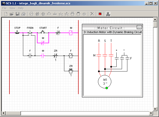
Print circuit
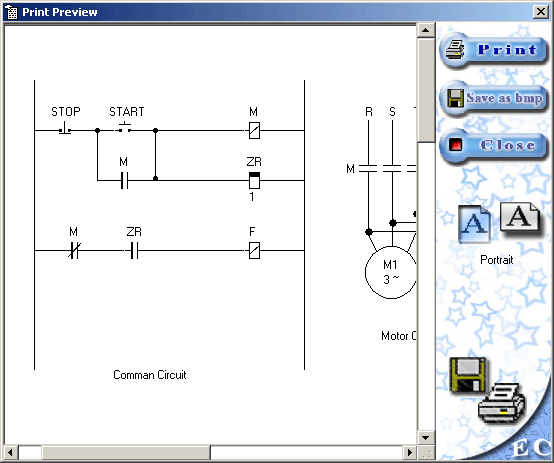
To print designed circuit, click on  Print button. Print preview dialog window will appear. There you can adjust paper position and locations of command and motor circuits on paper. To specify paper position, select landscape or portrait position from right side menu. To move command or motor circuit simply drag and drop them on desired position. Also it is possible to save print outs as image in BMP format.
Print button. Print preview dialog window will appear. There you can adjust paper position and locations of command and motor circuits on paper. To specify paper position, select landscape or portrait position from right side menu. To move command or motor circuit simply drag and drop them on desired position. Also it is possible to save print outs as image in BMP format.Electromechanical Systems Simulator Examples
1. Button lock circuit.
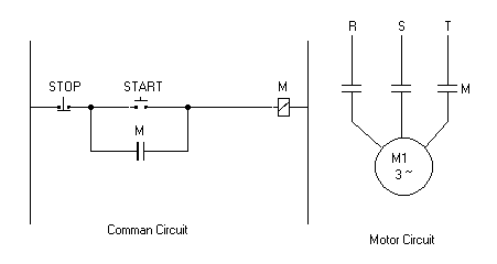
This circuit shows how to use relay contact to lock button position. When “START” button pressed “M” relay activates and motor starts to rotate. At the same time one contact of relay “M” locks start button so that current continue to pass through relay “M”. Stop button is used to cut the energy from relay “M”, which will cut energy from motor.
2. Remote control circuit
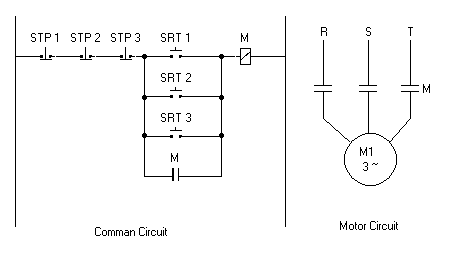
This circuit is used to control motor from different locations. All stop buttons connected serially and start buttons connected parallel to each other. We can start and stop motor by using any start and stop buttons from any location.
3. Starter circuit for one phase Asynchronous Motor
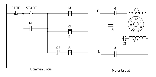
This circuit is used to start one phase asynchronous motor. By pressing start button “A” and “M” relays activated and motor starts to rotate. At the same time, timer “ZR” activates and starts to count. When timer finishes counting, relay “A” is cut off energy by the contactor of time relay and motor continues to rotate without auxiliary winding.
4. Motor Starter circuit with single resistance
When the stator windings of an induction motor are connected directly to its 3-phase supply, a very large current (5-8 times full load current) flows initially. This surge current reduces as the motor accelerates up to its running speed. When very large motors are started direct-on-line they cause a disturbance of voltage (voltage dip) on the supply lines due to the large starting current surge. This voltage disturbance may result in the malfunction of other electrical equipment connected to the supply. To limit the starting current some large induction motors are started at reduced voltage and then have the full supply voltage reconnected when they have run up to near rated speed.
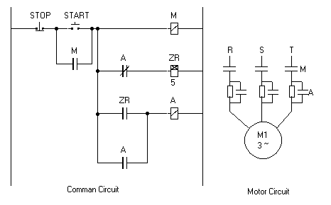
This circuit is used to start high power induction motors. When we click on start button “M” relay and “ZR” time relay activated.
Contactors of relay “M” connect motor to 3 phase power supply and auxiliary contact used to keep relay in power. Motor voltage is reduced by resistances serially connected to motor. Time relay “ZR” starts to count down. When time relay finishes counting, relay “A” is activated by contactor of time relay. Contactors of relay “A” bypass resistances used in motor circuit and motor continues rotating with full supply voltage. Timer of time relay “ZR” must be arranged to count until motor gets to rated speed. Button Stop is used to cut power off from motor and all relays used in command circuit.
5. Motor starter circuit with double resistance
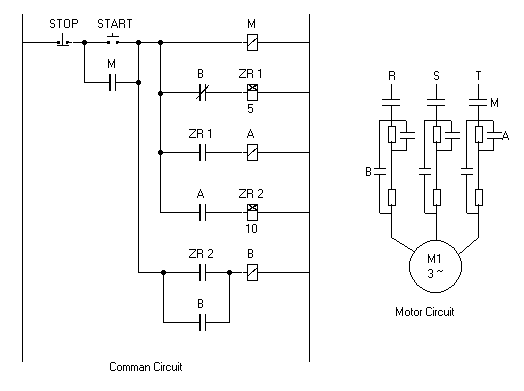
High power motors always need starter circuit for starting to work. When we click on start button motor starts to work with low voltage because of usage of two resistances. First timer starts to count to specified time. When timer finishes counting relay “A” activates which used to bypass first resistance in motor circuit and starts second timer. When second timer finishes counting relay “B” activates and both resistances bypassed in motor circuit.
6. Star- Delta starter circuit
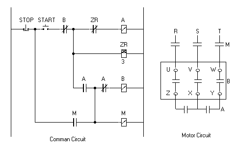
This circuit is used to start motor working using star connection for some period and then switch to delta connection. This method is used to start high power motors. When we click on “START” button, “A” relay is activated and its contact activates relay “M”, which connects motor to power supply. Other contacts of relay “A” connect motor windings in star connection. Motor starts rotate using low voltage. Time relay “ZR” is also activated by “START” button. When time relay finishes counting its normally closed contact activates and relay “A” is deactivated, which activates relay “B”. Relay “B” converts motor connection type to delta. Auxiliary contact of relay “B” deactivates time relay “ZR”. When we click on “STOP” button all relays deactivated and motor circuit cut off power supply.
7. Changing rotation direction with protection lock
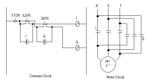
We have two buttons to rotate motor in separate directions. “ILERI” button activates Relay “I” which rotates motor in forward direction and “GERI” button activates relay “G” which rotates motor in backward direction. At the same time button “ILERI” is used to cut energy from relay “G”, in case it was activated, before activating relay “I”. This is preventing from short circuit in motor circuit. Button “GERI” is also used in the same way. Button “STOP” is used to cut energy from both relays “I” and “G”, which cuts energy from motor.
8. Changing rotation direction with electric lock
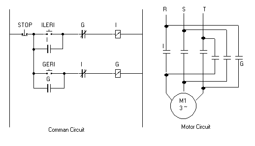
To rotate motor in selected direction press “ILERI” or “GERI” buttons. While motor is rotating in one direction it is electrically impossible to rotate it in another direction without stopping it. If you try to change direction of rotation while it is rotating in one direction Command circuit will not activate related relay because of security contact. For example we start rotate motor in forward direction by pressing “ILERI” button. Relay “I” is activated and motor starts to rotate. Normally closed contact of relay “I” located before relay “G” will prevent activation of relay “G”. Therefore we have to stop motor by clicking “STOP” button and deactivate active relay “I” in case to rotate motor in reverse direction.
9. Dynamic forced braking
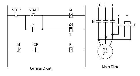
When we cut off energy from motor it doesn’t stop immediately. It continues rotating while it looses its kinetic energy. To stop motor immediately dynamic barking circuit is used.
In command circuit when we click on start button relay “M” and inverse time relay “ZR” is activated. Motor connected to power supply by contacts of relay “M”. When we click “STOP” button relay “M” and inverse time relay “ZR” is deactivated. Motor cut off energy. Counter of inverse time relay starts to count down. Contact of inverse time relay “ZR” is remaining active while counter counts down. It activates relay “F” which connects motor to braking circuit. When inverse time relay finishes counting, its contact became inactive, that deactivates relay “F”. Motor is cut off braking power supply and remains fully sopped.
10. Optional dynamic braking
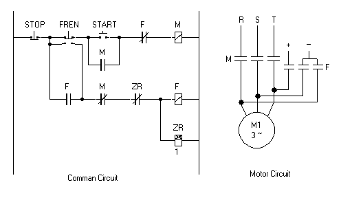
This circuit have optional dynamic braking button “FREN”. Start motor rotation by pressing “START” button. To stop it we have two choices. First by pressing “FREN” button which will cut main power and apply braking circuit to motor for short period. Second by pressing “STOP” button which will just cut power from motor circuit.
11. Continuous and Discontinuous working motor circuit
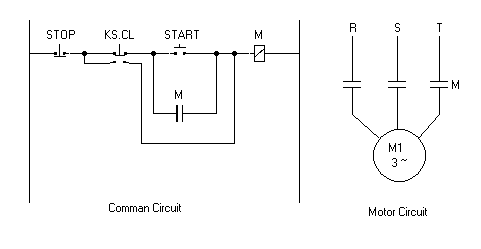
This circuit explains how control motor for continuous or discontinuous working. By pressing “START” button we make motor work continuously. Relay “M” is used to rotate motor and lock start button. By pressing “KS.CL” button we use relay “M” just for rotating motor.
When we release “KS.CL” button “M” relay energy will be cut off and motor will stop. “STOP” button is used to stop motor in continuous working mode.
Info
Supervised by
Hasan ERDAL
Department of Control Education, Marmara University , Istanbul, Turkiye
E-mail: herdal { at } marmara.edu.tr
Programmed and developed by
Vepa Halliyev
E-mail: vepa_hall { at } yahoo.com
Simulator was published as Graduation project.
© Publication name: ELEKTRİK KUMANDA TEKNİKLERİ
DERSİ SIMULATÖR PROGRAMI TASARIMI
Publication date: 2002
Place: Marmara University , Technical Education Faculty, department
of Computer and Control Technologies, Istanbul , Turkiye.Web: www.marmara.edu.tr